Online STEP viewer and browser tools for 3D and CAD files
Model-based definition (MBD) keeps dimensions, tolerances and notes in the 3D model itself. These tools open that model, create it from a drawing and add to it, with no CAD seat and no install.
Open full 3D STEP assemblies in the browser
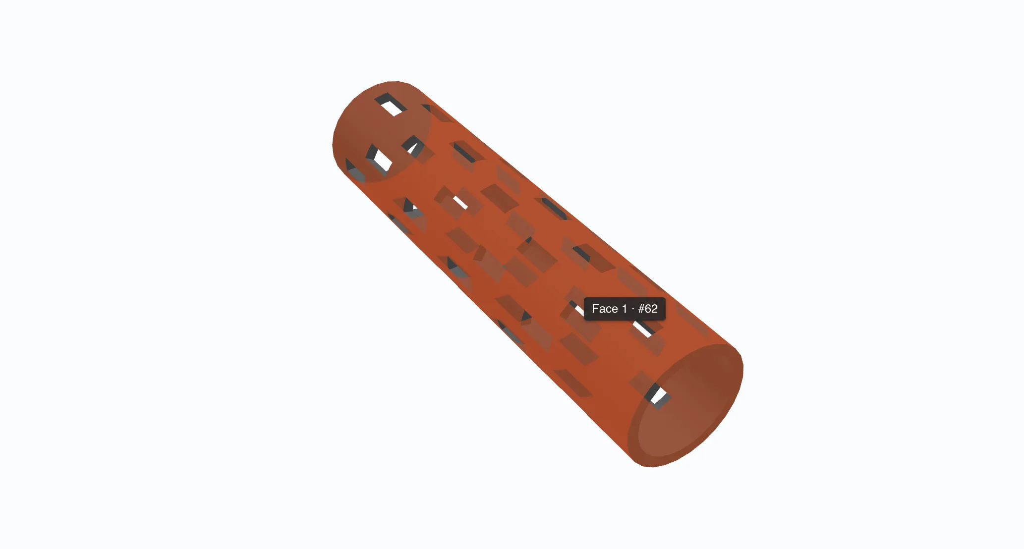
CUTL opens full 3D STEP models right in the browser. Rotate, zoom, section and explode the assembly, and read everything the file already carries: no CAD seats, no exported screenshots, no converting to a neutral format first.
You and your client discuss the part together
Invite your customer in to look at the same part with you. Pin comments, talk through the assembly live and agree on it in one place, with no endless email threads. When everyone agrees, push it straight to quoting.
Fix DXF geometry and fold it into 3D, in the browser
Open any DXF, let AI clean the geometry, set bend lines and convert it to a folded 3D STEP model, without leaving the browser.
Any starting point
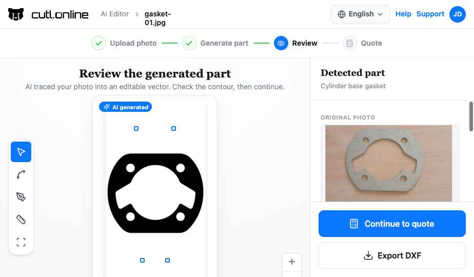
Your own DXF, a text description, a common shape or a photo of a part. All open in the same editor.
Bring your own DXF, describe the part and let AI draw it, start from a common shape, or photograph a part on the shop floor. Every route ends in the same editor, and every drawing in it can be converted to a folded 3D model without leaving the part editor.
Bend lines
Each bend has its own angle, direction and inner radius, calculated from material, thickness and K-factor.
Draw bend lines where the part folds and each one carries its own angle, direction and inner radius. The fold is calculated from the sheet: the part's material and thickness, its K-factor or an explicit bend deduction per bend. Convert, and the blank is folded along those lines into a solid you can inspect. A part with no bend lines is extruded to its sheet thickness with the holes cut through, which is all a flat laser part needs.
Refuses what cannot be bent
Bend lines that do not cross the part, angles outside 10° to 170° and crossing folds are blocked in the editor, not on the press brake.
A bend line that does not fully cross the part turns red and blocks the conversion, an angle outside 10° to 170° is rejected, and crossing folds are refused with the reason. You find out in the editor, in seconds, rather than on the press brake.
Turn a PDF drawing into a 3D STEP model
Upload a PDF drawing and get a 3D STEP model back, usually in 10 to 30 minutes. No tracing and no setup. Close the page if you like: we email you if we need you.
Reads the drawing like an engineer
Finds the views, measures the outline and holes, reads dimensions and fold lines. Units, scale and projection are detected for you.
The conversion finds the views and works out how they relate, measures the outline and the holes, reads the dimensions and the fold lines, then builds the solid from a fold recipe. Units, scale and projection are detected from the drawing itself. If you already know them, declare them up front and skip the guesswork.
Asks instead of guessing
If a drawing is unclear, the run pauses and asks one specific question. Answer in the browser and it carries on.
When a drawing is genuinely unclear, the run stops and asks one specific question rather than handing you a wrong model: ambiguous units, a missing scale, two section views that contradict each other, unreadable fold lines, an unproven thickness. You answer in the browser and the run continues where it paused. Every reading it made is there to inspect alongside the drawing before you approve it.
Lands in your STEP library
Ready to view, nest, price and quote, and to enrich with PMI.
The result lands in your STEP library, ready to view, nest, price and quote, and to enrich with PMI. A drawing nobody can read stays a question rather than becoming a bad part.
Put tolerances in the model, not beside it
Put GD&T, dimensions, datums, finishes and certificates into the STEP file itself, readable by the next machine and the next supplier. Add them by hand or import them from a spreadsheet, a QIF file or the drawing PDF.
PMI is for the team that owns the model. Invited reviewers see comments and the model, not the PMI panel.
GD&T checked as you type
ISO 1101 or ASME Y14.5, with 31 rules enforced before a frame can be added. Mark criticality per requirement.
Pick the characteristic, the tolerance zone and its form, the datums with their modifiers, a composite frame's lower segments, and whether it applies to one face, a pattern of features, the whole part or every instance of it. Mark what matters most with a criticality level and the designator your customer's inspection report is read against. Set the drawing standard once per part, ISO 1101 or ASME Y14.5 with its general tolerance class, and every frame is checked against that standard's rules as you type. A form tolerance cannot reference a datum, and the panel says so in words instead of letting a bad callout reach the file.
Import a requirements list
From a spreadsheet, a QIF file or the drawing PDF. Accept, edit or reject each row, with an audit trail.
Point it at a spreadsheet, a QIF file or the drawing PDF and each requirement becomes a row to accept, re-place, edit or reject. The review runs in rounds, one decision covering every instance of a part, with an append-only, hash-linked record of who decided what and when. That is the evidence an audit asks for, produced as a by-product of the work.
Four outputs from one set
Enriched STEP, a QIF inspection program for PC-DMIS, Calypso or Verisurf, a ballooned drawing and an inspection report.
Saving writes a new version of the model and reports, requirement by requirement, what happened: written as semantic PMI, drawn as a callout, or refused with the reason. You stay on the version you were reading until you choose to move. Out come an enriched STEP model, a QIF inspection program for PC-DMIS, Calypso or Verisurf, a ballooned drawing and an inspection report: one requirement set in the four forms the supply chain asks for.
Documentation from a 3D model, generated for you
An assistant built right into the STEP viewer turns a 3D assembly into a finished document. It breaks the model into parts, reads everything the file already knows, and asks only what is missing, then builds a parts list and a page per part as a PDF or editable DOCX, in your company template.
Open your first STEP model in the browser
Looking at a file needs no account. Create a free one when you want to keep it, share it with a client or use the other tools.